"The day was really well put together and the feedback from the team has been very positive. The training, innovation centre and factory tour were all very worthwhile and gave the group a much better understanding of the importance of tested details, interfaces and the wider fire stopping strategy."
 On
15
https://www.linkedin.com/in/joel-glowacki-534406392/
On
15
https://www.linkedin.com/in/joel-glowacki-534406392/
Insights from UK Construction Week: Why connection is now critical to construction performance
UK Construction Week London 2026 reinforced its position as the UK’s most influential construction and built environment event bringing together ministers, policymakers and industry leaders to engage directly with the sector on its biggest challenges.
Co-located with Futurebuild and the Stone & Surfaces Show, the event delivered three high-energy days of debate, innovation and collaboration covering housing, infrastructure, planning, skills, retrofit and economic growth. With packed aisles, standing-room-only theatres and high-level networking throughout, it remains unmatched in its ability to bring together government engagement, industry influence and market reach under one roof.
Against this backdrop, UKCW highlighted a sector under increasing pressure to connect across systems, disciplines and information. From façade integration to AI-driven discovery, delivering better buildings increasingly depends on clarity, collaboration and a system-led approach.
This year’s event reflected an industry under pressure to evolve - driven by stricter regulation, increasing technical complexity, advancing AI technologies and a growing demand for demonstrable performance. For Siderise, our presence across two sessions reinforced a clear and consistent message:
“Better buildings depend on better connection - between systems, between disciplines, and between the people designing and delivering them.”
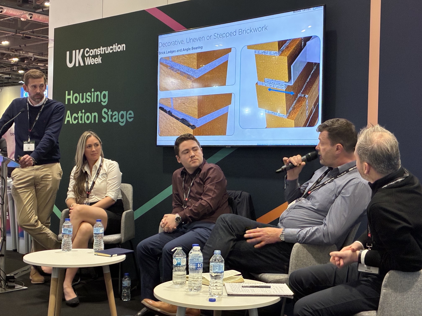
Looking beyond components: a system-led view of external masonry wall design
A highlight from UKCW was our participation in the panel ‘Inside the Wall: Delivering Safe, Compliant Masonry Façades for High-Rise Housing.’
In collaboration with Leviat and Ibstock, this session explored the wall not as a series of individual products, but as a fully integrated system from structural elements through to passive fire protection and moisture management.
This ‘through-the-wall’ perspective is critical. In practice, performance is rarely determined by a single element. It is most often defined at junction interfaces: where systems meet, complexity increases, and risk accumulates.
The panel reinforced a simple but important principle: when we design in silos, we create gaps; when we design as systems, we reduce them.
Across both our panel and wider discussions at UKCW, one theme came through consistently: the earlier collaboration happens on a project, the better the outcome.
The challenges the industry faces today in terms of compliance with the Building Safety Act, increasing scrutiny on product performance, and more complex façade typologies are difficult to resolve late in the process. They must be addressed at the point of design intent. A more integrated approach supports:
Clearer detailing, reducing ambiguity at interfaces.
Fewer clashes onsite, improving buildability.
Better alignment between design, specification and installation.
Greater confidence in performance across the building lifecycle.
This is not just best practice, it is fundamental to delivering safe, compliant and high-performing façades.
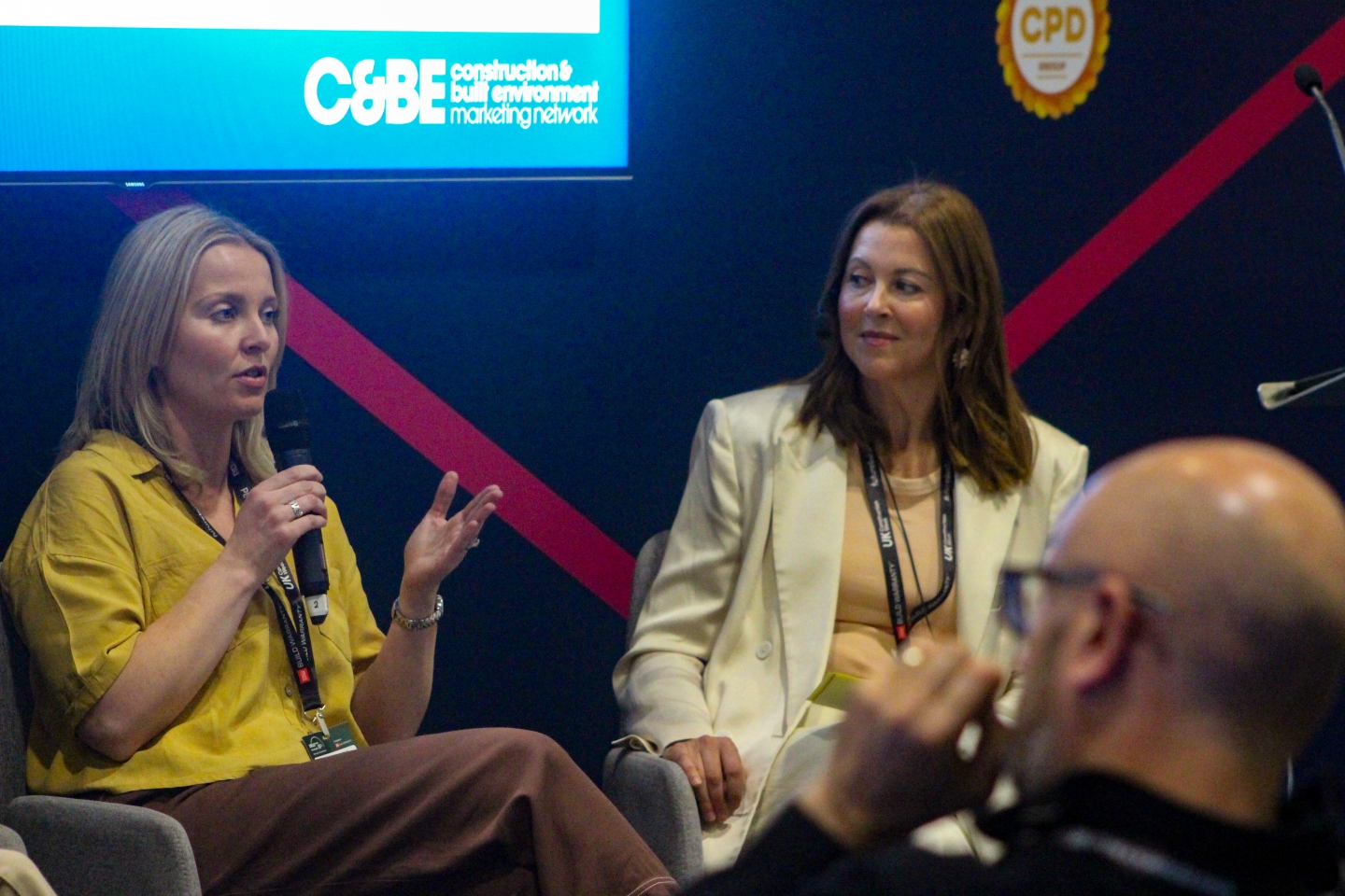
Beyond specification: communication in the age of AI
It was fantastic to see UKCW introduce the new Marketing and Procurement stage, offering a dedicated space for these crucial disciplines to discuss their journeys and influence in the built environment.
Our Marketing Director, Penny Howell-Jones, proudly partook in a panel at the inaugural Marketing stage, for a discussion on ’AI, search and zero-click: what is keeping marketers awake at night?’
This Marketing-led discourse a saw UKCW highlight a shift in how construction organisations communicate - by exploring the intersection of brand, demand and artificial intelligence.
These themes align with wider industry insight from SLG Marketing’s Horizon 2026 Report, which points to a sector navigating increasing complexity in both how products are specified - and how they are understood.
The construction buying journey is no longer linear. Decisions are shaped earlier, often across multi-disciplinary teams with different priorities and levels of technical understanding. This means influence increasingly happens before direct engagement.
At the same time, the role of brand is evolving. It is no longer simply about visibility, but about trust - particularly where technical solutions appear similar. In this context, brand becomes the accumulation of:
Technical expertise.
Consistency and clarity of information.
Proven application through real-world case studies.
Ongoing meaningful and reliable support across the project lifecycle.
Artificial intelligence is accelerating this shift. As digital discovery evolves, technical content is no longer simply searched, it is interpreted, summarised and compared across sources.
For manufacturers, this raises the bar. Intensified by the government’s current construction products reform affecting product information, content not only has to be technically accurate and unambiguous, but it must also be consistent across platforms and touchpoints, and structured to support interpretation. At a time, which sees a serious overlap of rapid AI adoption vs. AI accuracy, it is fair to say that unclear or inconsistent information introduces more risk than ever.
Kate Perrin, Marketing Director of Barbour ABI said:
"Attending UKCW/Futurebuild last week was rewarding, especially with the marketing agenda finally being placed front and centre where it belongs.
A personal highlight was chairing a panel of marketing leaders, including Penny Howell-Jones from Siderise. Together we dove deep into the world of AI and tackled the burning questions of what is currently keeping constrction marketers awake at night. It’s clear that our industry is at a massive turning point, and marketing is poised to lead the charge."
Looking ahead: connection as a defining principle
If there is a single takeaway for us from UK Construction Week 2026, it is that connection is now a defining principle of construction performance.
Connection between disciplines to reduce risk.
Connection between systems to ensure performance in practice.
Connection between people and information to support competent decision making
For Siderise, this fuels our mission to ‘Go Beyond, contributing to safer buildings’. We are dedicated to supporting the construction industry with unparalleled technical insight, collaboration across the entire project lifecycle and a system-led approach to deliver safer, more robust buildings.
Contact us
We're here to help you
Call for our main switchboard
Email us for technical enquiries
Email us for site support
Complete the form for the right response
Code for Construction Product Information in 2026 – where the scheme is up to and Siderise’s journey to the CCPI Mark
We have recently announced that we have successfully undergone the two-year review process for our CW-FS Firestop and had new ranges assessed under the Code for Construction Product Information (CCPI). At this milestone, we wanted to reflect on the influence of the CCPI on the construction sector’s expectations and use of product information, and share some of our own insights as we seek to further embed the Code’s call for “clear, accurate, up-to-date, accessible and unambiguous” product data into our everyday processes and our culture.
What is the Code for Construction Product Information?
The CCPI was created by the Construction Product Association (CPA)’s Marketing Integrity Group, which at the time was chaired by Siderise CEO Adam Turk, in response to calls for clearer labelling and marketing of construction products to support accurate specification. As Adam explained in 2023:
“Whilst it is the specifier’s responsibility to select the correct product for their project, the onus is on manufacturers to make this as straightforward as possible for them. This means providing accurate and up-to-date product information that is accessible and unambiguous in its language. Any fire performance claims should be backed up with relevant test data and third-party certification found easily online or through technical support channels.”
Now established, the Code is overseen by Construction Product Information Ltd, a not-for-profit organisation that is independently governed and headed by Chief Executive, Amanda Long.
We explore what the CCPI means for specifiers in more detail in our Insights Blog: CCPI mark – what does it mean for specifiers of our products?
How has the Code for Construction Information been adopted?
Since its launch, the CCPI has gained real momentum in its aim to “raise standards in construction product information and marketing and drive positive culture change.” It has not only provided welcome guidance at a product level but has been highlighted as an example of best practice by leading industry bodies, such as:
The Chartered Institute of Building (CIOB)- committed to support and promote the CCPI, including in its 2025 Guide to Products Critical to Safe Construction.
Royal Institute of British Architects (RIBA)- committed to promote the work of the CCPI to its members in its formal response to Grenfell Tower Phase 2 report recommendations.
Construction Leadership Council (CLC) - includes CCPI as a central element of its Building Safety Workstream.
Chartered Institute of Architectural Technologists (CIAT) - CCPI Organisation Associate to support the code and registration across its membership and network
Association for Specialist Fire Protection (ASFP) – one of the first to become a CCPI Trade Associate, the ASFP has made CCPI a key criterion for manufacturer members to achieve ASFP Pass Mark.
Get it Right Initiative (GIRI) - the CCPI has become a member of GIRI – an industry-led organisation dedicated to eliminating error and improving the UK construction industry.
Significantly, the Code has also been referenced and supported at a governmental level:
It was recommended for implementation by the ‘Independent Review of Construction Product Testing’ led by Paul Morrell OBE and Anneliese Day KC.
The CCPI is referenced in the Construction Products Reform Green Paper 2025 as an example of industry-led best practice including calls for “industry to significantly increase the take up of initiatives such as this Code.”
The Construction Playbook: Government Guidance on sourcing and contracting public works projects and programmes also “strongly encourage compliance and implementation” of building safety initiatives such as the CCPI.
PAS 2000: 2026 Construction products – Bringing safe products to market –
Code of practice, sponsored by the Office for Product Safety and Standards (OPSS) – Clause 8 ‘Safety in construction product information’.
It is therefore unsurprising that, by the end of 2025, there were 150+ companies registered with CCPI and 3000+ products are now under CCPI Assessed Mark, with 100% of companies undergoing the two-yearly reassessment. What’s more, the Code has evolved to include a separate Code for merchants and distributors and Demand-Side Supporters— companies that use or specify products in the construction and maintenance of the built environment who publicly pledge to champion the Code’s aims to raise standards of product information and deploy CCPI-Marked products where possible.
Siderise and the Code for Construction Product Information
We were one of the first manufacturers to declare our support for the CCPI in 2021 and our CW-FS Firestop product set for curtain walling was one of the first ranges to go through the scheme’s rigorous and independent assessment process in 2023. Whilst resource intensive, we believe the rigorous assessment framework is essential for rebuilding trust and raising standards in our sector and are fully committed to its requirements.
Products
Since 2023 we have gained the CCPI Mark for all our core life-safety critical product ranges and some of our acoustic solutions, including:
CW-CB Cavity Barrier and CW-FS Firestop for curtain wall applications
RH Horizontal and RV Vertical Cavity Barrier for cladding applications
CT Cavity Tray and EW Cavity Barrier and Firestop for masonry external walls
CW-AB Acoustic Barrier and CW-FB Fireboard for curtain walling
IC-FS Firestop and IC-CB Cavity Barrier for industrial cladding
We have also aligned the process of getting the CCPI Mark for our core products with developing a more holistic specification support package, including creating Specification Packs that summarise the relevant product information for the designated application. In addition, we have invested in building our partnership with specification platforms such as NBS, which has integrated new functionality into its platform to help specifiers identify and select CCPI registered products.
Leadership and processes
A key part of the CCPI assessment process is its review of the Leadership and Culture surrounding the creation, maintenance and distribution of product safety and information. This is repeated every two-years to ensure high standards are continuously upheld.
Our 2025 reassessment report, which included summarising survey responses from 41 randomly selected employees about the company’s approach, highlighted that there is “a common understanding that Siderise has a strong culture of “doing the right thing,” almost at all costs. This sentiment was consistently expressed in the discussions, particularly regarding fire safety.”
It also stated that: “Those spoken to consistently expressed a view that Siderise strives to provide the highest quality, safest products, and accurate product information. They also emphasised the strong emphasis on “Integrity” in the daily work, which appears to stem from Siderise senior leadership.”
Competency
Of course, there is no point providing high-quality product information if the people creating, sharing and eventually using it do not have the right skills, knowledge or behaviour to do so. In addition to enhancing our external training provision— including becoming the first ASFP Recognised Training Provider in 2024 and launching the Siderise Academy and Online Learning Portal in 2025— we have invested heavily in raising our internal competency levels.
Our internal competency program goes beyond what is typical in the industry. We have assessed all job roles using a SKEB matrix (Skills, Knowledge, Experience and Behaviour). Following this, our customer-facing employees undergo formalised training to ensure sufficient product knowledge, with ongoing upskilling for technical staff and professional qualifications. Progress is tracked and managed by a dedicated training team.
This helps to ensure that our customer service is delivered by informed and engaged people who have the right tools to deliver accurate and accessible information at every stage of the construction process.
Explore our specification support services.
Contact us
We're here to help you
Call for our main switchboard
Email us for technical enquiries
Email us for site support
Complete the form for the right response
 On
-4
https://www.linkedin.com/in/courtney-thomas-476b21327/
On
-4
https://www.linkedin.com/in/courtney-thomas-476b21327/
 On
-10
https://www.linkedin.com/in/elliott-slocombe/
On
-10
https://www.linkedin.com/in/elliott-slocombe/
 On
15
https://www.linkedin.com/in/nicola-franks-776155313/
On
15
https://www.linkedin.com/in/nicola-franks-776155313/
 On
-10
https://www.linkedin.com/in/peter-rodgers-abb226143/
On
-10
https://www.linkedin.com/in/peter-rodgers-abb226143/
What is the difference between one-part and two-part
firestopping systems for curtain walls?
Fire safety in glazed façade systems is a critical consideration—particularly in multistorey commercial and residential buildings. At the slab edge, firestopping plays a vital role in maintaining the integrity of the compartment floor by extending its fire resistance to the façade rear, helping to prevent fire from spreading vertically between storeys and supporting compliance with various fire and building codes and regulations.
In this insights piece, we explain the performance differences between one-part and two-part perimeter joint firestopping systems to help project teams assess the most suitable option for curtain wall applications
There are two types of curtain wall perimeter fire barrier solutions commonly available on the market. They can be broadly categorised into one-part dry-fit firestop systems and two-part safing-and-sealant firestop systems (also known as two-part pack-and-spray systems). While both approaches can achieve regulation and code compliance, the choice of system can significantly influence factors such as fire resistance and durability, installation speed and accuracy, long-term resilience, and ease of inspection and repeatability—making product choice a strategic decision on all kinds of projects.
What are one-part and two-part firestops?
Two-part pack-and-spray systems
Traditional approaches to firestopping at the façade / floor slab interface require the installation to be carried out in two separate stages:
Manually compressing generic mineral wool firesafing insulation (typically at 25% or 33% compression depending listing requirements) before installing it within the movement gap at the perimeter construction joint.
Applying a wet sealant such as a spray-applied fire-rated silicone or elastomer over the top of the safing to create a moisture resistant smoke barrier once cured.
NB It is important to note that whilst the terms firesafing and firestopping are sometimes used interchangeably, they do mean two very different things. In this context, firesafing is where a fire-resistant material is used to fill the void to insulate against heat transfer and prevent fire spread but does not have a fire-resistance rating for the designated application in and of itself i.e. it is one component of a firestop system, and it is the assembly that is fire rated - hence the description ‘two-part’.
Firestopping is where a material or combination thereof is used to continue the fire resistance of the floor slab and act as a barrier to the passage of flames and hot gases between compartments.
One-part dry-fit systems
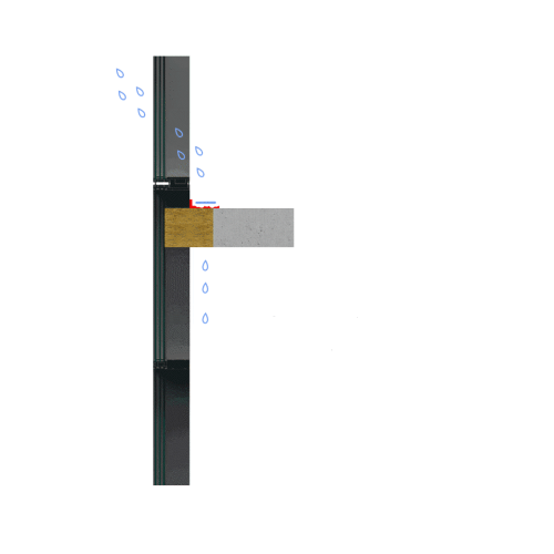
One-part dry-fit systems, such as the Siderise CW-FS Firestop, feature factory-engineered stone wool Lamella insulation with foil facings applied to the cut surfaces of pre-compressed vertically oriented fibres to retain the ‘built-in compression’ and assist with uniformity of product density. Designed and tested to provide a robust fire and smoke seal in the perimeter void between the façade and compartment floor, without the need for a topical wet sealant, they are installed in a single-fix with additional manual compression (usually 10% or 20% depending on test certification / listing compliance requirements) for a tight fit and to accommodate movement at the floor slab / curtain wall interface.
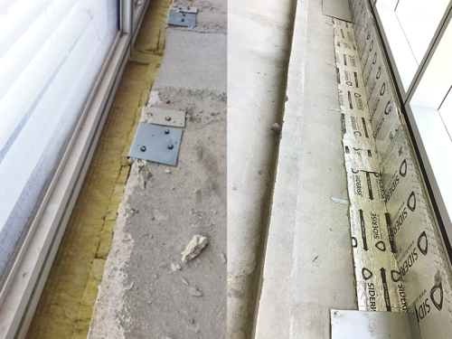
The Siderise one-part-dry fix system and the safing component of a two-part spray and pack system at the curtain wall / floor slab intersection.
What are the benefits of one-part dry-fit systems over two-part firestops?
Ease of specification
One-part dry-fit firestops can be ordered pre-cut to suit the cavity width and can be supplied as part of a complete system package from a single manufacturer with spandrel insulation, mullion and transom fire protection, plus ancillary components. These products are often tested together in multiple test scenarios, and third-party certified as a perimeter fire containment system for effective passive fire protection in the spandrel zone.
Two-part wet-seal systems require a firesafing material and an appropriate sealant to be specified. To comply with the criteria of any third-party approvals or listings published by the sealant manufacturer, the safing insulation product should always be the same as that used in the certified tested system. Using substitution products risks undermining the specified fire resistance performance of the complete firestopping assembly, resulting in non-compliance.
Resilience, durability and fire performance
As we explore in this Insights blog, firestops installed within curtain walling systems must be durable enough to maintain their form and fit, even when subjected to façade and floor slab movement. The safing insulation component of two-part firestop systems typically comprises standard mineral wool insulation with horizontally oriented fibres. Most certification listings call for cut sections to be rotated 90° by the installation operative to reorient the fibres so that they run vertical to the floor slab when installed. If this does not take place, the fibres will run parallel and while this transverse alignment offers stability, continual exposure to building / façade movement makes the material more susceptible to degradation along its length, resulting in the fibre structure breaking down. This means that the ability of the safing material to recover from repeated compression cycles in-service is reduced.
This can lead to the firesafing no longer maintaining the compression fit, increasing the risk of a gap forming between the product and the façade over time. Should this occur, the perimeter seal could fail prematurely, resulting in loss of compartmentation.
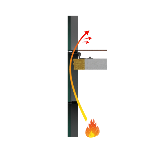
Gaps will form between the curtain wall and the firestop if the safing material is unable to withstand stresses and strains from building and facade movement.
Meanwhile, one-part firestops with a stone wool Lamella composition comprise vertically oriented fibres that run parallel to the substrate when installed. Products with a vertical fibre orientation are highly compressible and flexible laterally (across their width), which enables them to not only overcome challenges presented by curved and inclined façades much more easily, but accommodate the dynamic movement of the curtain wall or floor slab for their designed life.
Due to their unique structure, Lamella firestops maintain their ability to recover throughout their design life, as demonstrated through extensive age and movement cycling testing. This means that the seal is continuously maintained throughout the lifetime of the building and for the required fire resistance period in the event of a fire. When exposed to fire, the foil facing is designed to delaminate from the stone wool Lamella core, allowing the built-in compression to be released. This enables the product to expand and maintain its compression fit and integrity, even under the greater thermal stresses caused by the fire load that leads to facade and floor slab deflection.
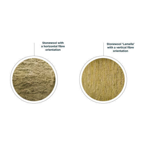
Safing with a horizontal fibre orientation is resistant to lateral compression, whilst products with a vertical fibre orientation are highly compressible.
Both system types can be tested to UL 2079 for air leakage, determined as the L-rating, to simulate smoke movement through compartmentation in buildings. Leakage testing can assist authorities in determining the suitability of firestopping systems for the protection of floor openings and smoke barriers for the purpose of restricting the movement of smoke in accordance with the NFPA (National Fire Protection Association) 101 Life Safety Code.
The difference between two-part spray and pack systems and one-part dry-fit systems is that the latter does not rely on a wet seal to provide an adequate L rating.
UL 2079 tests for air leakage to simulate smoke movement through compartmentation in buildings.
Application and storage conditions
During storage, application and curing, the wet seal compound in two-part perimeter barrier systems is temperature-dependent and moisture-sensitive. This can be a challenge during hot seasons or locations with frequent rainfall — otherwise adhesion, curing, design life and product integrity may be adversely affected. In most cases, the maximum application temperature is typically limited to 40°C (104°F) as high heat can cause rapid skinning or premature curing, making tooling difficult and reducing adhesion. They also must be stored between 5 and 25°C (40 and 80°F), which can require onsite storage facilities with a controlled environment, particularly in regions prone to inclement weather. Improper storage can reduce workability if the sealant has thickened, shorten open time and curing consistency, and compromise the fire rating performance due to chemical degradation.
Two-part dry-fix systems simply require a dry and clean surface to fix them to and can be stored onsite in a general sheltered area to prevent rainwater damage.
Installation process
A common installation error with the safing component of two-part systems is the material not being rotated so that the fibres sit perpendicular to the slab edge before being installed, which, as mentioned earlier, negatively impacts durability thus performance.
Before installing the smoke barrier of two-part wet-seal systems, surfaces must be prepared with extra care to allow adequate bonding and even curing. The wet compound must then be applied with a consistent thickness, in line with system testing as any variations in thickness that fail to meet the specified tested system design risks rendering it non-compliant. Transporting and setting up heavy spray rigs, with specialist equipment such as pumps and mixers, can be time-consuming as can labour intensive manual methods such as portable hand sprays or application by hand, while tight slab-edge zones often lack room for bulky equipment.
In addition to having to wait for the right application conditions, the ‘curing’ and messy overspray clean up time needs to be accounted for in the project schedule. This installer-driven and weather-dependent approach can also make it challenging to achieve a replicable and verifiable level of quality across whole buildings of multiple storeys, creating bottlenecks.
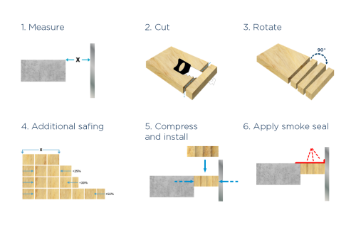
Typical installation process for two-part safing-sealant systems
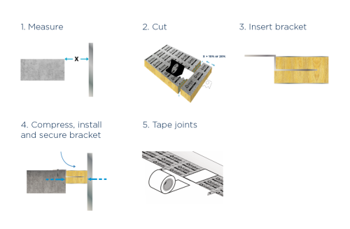
Typical installation process for one-part dry-fix perimeter firestopping systems
In contrast, one-part dry-fit firestops are not as weather or temperature-sensitive and do not require any specialist application equipment or highly intensive surface preparation of the substrate. There are no curing times, wet or dry-film thickness complications. Their straightforward installation approach, including a standardised compression percentage, can streamline the installation process and help reduce the risk of human error. They also provide greater freedom for the installer in areas where access to the firestop zone is difficult after the façade is installed. Dry-fit firestops can also be installed before the façade (including from the soffit).
Joints exposed to water during the installation phase of wet-applied smoke seals can result in ‘washout’.
Inspection
With two-part systems, once the wet seal is applied, verifying the correct dry-film thickness, adhesion, and safing orientation and compression ratio becomes impossible without destructive testing or a two-stage inspection, which means site operatives cannot immediately proceed with adjacent works, thus potentially holding up the build program.
Alternatively, when dry-fit, one-part firestops are installed, visual inspections are generally sufficient. The wrinkling of the foil makes it very easy to confirm if they have been installed under compression without disturbing the installation. Their dry-fit application also makes it easier to judge bracket locations and distances, and tight jointing to ensure a continuation of the fire performance around the perimeter.
A modern approach to protecting curtain walls
While traditional two-part firestop systems have been widely used all over the world, they often present challenges related to long-term durability, installation complexity, and inspection consistency. In contrast, one-part firestop systems that have been engineered and tested to key standards such as EN 1364-4, EN-1364-3 and ASTM E2307 offer a reliable alternative. By delivering uniform compression, accommodating façade movement, and enabling straightforward visual inspection, one-part dry-fit systems support code-compliant construction practices and help ensure consistent fire-resistance performance across every floor and project.
Discover more about our one-part dry-fit Siderise CW-FS Firestop.
Contact us
We're here to help you
Call for our main switchboard
Email us for technical enquiries
Email us for site support
Complete the form for the right response
HR in Wales Awards 2026
Winning the Learning and Development Award at the HR in Wales Awards 2026 marks a significant milestone for Siderise. This insight shares how a values‑led approach to leadership development is strengthening capability, confidence, and culture across the business.
What did Siderise win at the HR in Wales Awards 2026?
Siderise won the Learning and Development Award, recognising the impact of its leadership development approach. We were also shortlisted for the Individual Impact and Rising Star categories, reflecting the wider strength of our people and culture strategy.
Why did Siderise enter the awards?
Leadership development is a core part of Siderise’s long‑term commitment to building organisational capability, succession, and cultural confidence. Operating in a specialist manufacturing and life-safety critical construction product environment, we depend on strong, consistent leadership to support technical excellence, safety, collaboration, and performance.
Entering the awards provided an opportunity to benchmark this work externally and demonstrate how a values‑led, structured approach to learning can deliver tangible cultural and commercial outcomes.
What challenge was Siderise addressing?
When the leadership development journey began, Siderise lacked a consistent leadership framework and clear development pathways. Employee feedback highlighted gaps in leadership capability, and learning was not well connected to onboarding, performance management, or progression.
The challenge was to build a scalable, effective solution with a small internal L&D function - while still delivering meaningful change across the organisation.
It’s helped me understand how different parts of a façade system interact, especially at junctions which are often complex. I’m naturally curious about how things go together, and that’s shaped my approach to fire safety. While specialists bring deep technical insight, I think being a generalist allows me to connect the dots and ask different questions seeing things from different perspectives and raising additional considerations.
What approach did Siderise take?
Instead of introducing isolated programmes, Siderise built a connected values‑led leadership development ecosystem aligned to not only how we operate day‑to‑day but which also supported future readiness and a consistent leadership culture across the organisation.
This included:
Clear leadership pathways linked to career progression.
Three core programmes: ASPIRE (aspiring leaders), RISE (operational leaders) and ELEVATE (senior leaders and executives).
Short, practical learning embedded into everyday work.
Coaching and mentoring
Integration with onboarding, performance reviews, and succession planning.
External partnerships and funding were used strategically to extend impact, while maintaining strong internal ownership and cultural alignment.
What were the outcomes and how has this impacted the business?
Learning is now clearly linked to real‑world application and by moving away from ad‑hoc, compliance‑led training to structured leadership pathways, Siderise has strengthened leadership capability.
The result is a complete, scalable development framework supporting leadership capability at every level of the organisation. Leaders report greater confidence, clearer communication, and stronger decision‑making.
Crucially, employee feedback now positions development as a cultural strength rather than a concern, with learning embedded as a visible and valued part of working at Siderise. In addition, the credibility of L&D investment decisions and accepting people development as a strategic enabler has been reinforced.
Why is winning a HR in Wales Award significant?
Alongside the CIPD, the HR in Wales Awards are among the most respected HR awards in the country. They are judged independently by experienced HR and business leaders across multiple sectors, providing external validation and confidence for customers, partners and regulators.
The awards focus on impact, not activity—recognising what has genuinely changed and why it matters. Winning confirms that Siderise’s leadership development approach delivers measurable improvements in capability, confidence, and culture, strengthening credibility with colleagues, customers, partners, and regulators.
What does this win mean to Siderise?
“This award reflects Siderise’s commitment to developing its people in a thoughtful, practical, and inclusive way. Our leaders wanted clearer expectations and support that genuinely helps them in their day‑to‑day roles—not training for training’s sake.
Winning shows that strong, scalable leadership capability can be built even with limited internal resource, as long as learning is well designed and embedded into how the business works. I’m incredibly proud of how our leaders have embraced development and turned it into a positive driver of culture, confidence, and performance.”
— Gemma Littlejohns, L&D Business Partner
“When we set out to create a more professional and strategically aligned approach to learning and development, I never imagined it would lead so quickly to recognition like this. It’s a testament to the impact the strategy is already having across our business globally—and this is just the beginning.”
— Mark Hendy, Chief HR Officer
Contact us
We're here to help you
Call for our main switchboard
Email us for technical enquiries
Email us for site support
Complete the form for the right response